Custom telescope mount using harmonic drives and ESP32
svendewaerhert.com301 points by waerhert 2 days ago
301 points by waerhert 2 days ago
Amazing project and write up, very good timing too! I’ve been into amateur astronomy since I was 13, owning a few telescopes and spending many hours with family at star parties.
This week I pulled out our big Meade 10” SCT and our small Meade 4” Newtonian to show my 7yo son the moon and Saturn from my parents Bortle 8 backyard. It was wonderful seeing his awe and surprise, and the fact that my parents were there to see it too.
That 10” SCT is on an old fork mount which is motorized but has no GOTO capabilities at all. I’ve also gone down the rabbit hole of researching mount options, thinking I could just buy my way out of it. However, as much as I like the idea of GOTO, a big part of the fun is finding the objects. So I’ve never been able to pull the trigger. I did buy a ZWO 585MC though, I’ve always wanted a dedicated cooled camera.
That said, we have lost way too many hours to trying to find objects. The Telrad isn’t always enough!
I’ve been looking into using my 3D printer and electronics know-how to build my way out of this. I was even thinking of swapping the motors for NEMA 17 steppers.
Then I stumbled upon PiFinder, and I think this project is going to be the exact balance of automation and Push-to guidance that I would like.
It’s a wonderful hobby and I think the latest in 3D printing and PCB manufacturing does mean we’re going to be able to solve a lot of these problems soon.
> Then I stumbled upon PiFinder
HorizonXP - I think you should submit this as a story/link!
>However, as much as I like the idea of GOTO, a big part of the fun is finding the objects.
I love reading this because it shows how different people are and how much room there is in the hobby for different interests. I am grateful for goto mounts specifically because finding the object is one of my least favorite parts of it. :D
Irony: I have a 1960s 100mm "Goto" refractor made by what is now the Goto planetarium company of Fuchu City, Tokyo. It's a headache to search for online. https://www.goto.co.jp/english/about/
Thanks! If you hook your ZWO up to Kstars/EKOS you can use plate-solving in software to find out exactly where your scope is pointed at and then adjust accordingly.
So a note on the capacitor bank. Basically the power cable from the USB-C supply acts as an inductor. Meaning, it has an LC (C from its capacities) filter which acts as a low-pass. The capacitors on-board basically are here to counteract that. If you think about it, let's say the motors do start taking a high amount of current. Where would it come from? In an instant, an inductor can't change how much current goes through it, so it'll basically look like an open. That's where the capacitors come in. They'll provide the current while the inductor is responding. Eventually the inductor will allow current flow out of the supply's capacitors.
One tiny nit on this amazing project / write up. He mentions that the traces have to be extra wide to support 24V. In truth though, the higher voltage means lower current, which means if anything the traces can be less wide. The size of the traces is determined by the current they carry, the voltage determines how much space must be between the traces (but it’s unlikely to be an issue at these voltages).
The IPC-2221A[1] specification standard, should have all the sizes/voltages/current for trace widths etc.
[1] https://www-eng.lbl.gov/~shuman/NEXT/CURRENT_DESIGN/TP/MATER...
I've been using freeCAD for about 3 years now. Looking at what he was able to make with it blows my mind. I love freeCAD, but I don't think I've ever been so continuously frustrated by a piece of software
Though very grateful for projects like FreeCAD, I did encounter a fair bit of frustration while designing this. Especially random crashes, which only got worse as the project got more complex. As far as usage goes, it's mostly a matter of knowing how to do things in FreeCAD. I haven't encountered anything I could not achieve in FreeCAD. Having no experience in other CAD software probably helped sticking to it.
I came to FreeCad with some years background in Inventor, NX and SolidWorks. The jump from any of these to FreeCAD is not very big; you're doing a lot of the same things. But, most of the problems FreeCad has are solved in those, so you can sort of do anything in them and be none the wiser. In FreeCAD, you need to think a little bit more on how it's going to do things.
But most people don't learn the big CADs first, they learn Fusion. The few times I've tried Fusion, it's given me a headache. It's probably a bigger headache going the other direction.
Then, there are those who do all their CAD work in OpenSCAD. They scare me.
OpenSCAD is great for functional parts, built of basic components. It can start to be good for moderate complexity components with the BOSL library (I use BOSL2) including chamfers/fillets where needed. And the parametric/customization aspect is second to none - IF it's built with that in mind.
Where it really falls down is when you need to somehow get data OUT of the model to feed to other shapes. I would love to be able to specify a chamfer or fillet along a contact edge of two other shapes, but unless you know the exact contact shape, location, and size a priori you will have a tough time getting anything to line up. If you want to use a mesh or model as a negative, every model's zero coordinate needs to be just right or it will just be entirely misaligned.
I've also tried to spend some time performance optimizing for render/output. It is not cooperative at all. It will just soak CPU time for a minute at a time for not even a complex shape! As pseudosudoer said, it really goes off the rails.
But for functional connectors, adapters, and replicating parts, it's great to be able to leverage my software skills in 3D modeling!
>I would love to be able to specify a chamfer or fillet along a contact edge of two other shapes
Yes, this is how the big cad programs work, they are 'constraint based'. You pick points and lines from other features (or other parts) and add whatever new geometry you want, and a solver fills in the rest. Features build off each other in this way. In OpenSCAD, you are the solver. But, the big programs have a ton of buttons, and scripting, while there, is usually hidden.
It's kind of like the difference between <insert image library> and Photoshop. Photoshop has a ton of useful tools inside, but if all you want to do is crop the bottom 30px from 2000 images, it's better to have a script do that. The scripts can technically do everything that Photoshop can do, but for other things it's easier just to click a few buttons and be done than reinvent the wheel from the ground up each time.
> I've also tried to spend some time performance optimizing for render/output. It is not cooperative at all.
Have you started using a recent nightly build with the Manifold backend and not the "stable" (aka obsolete) release?
I have not! I will give that a shot, and hope that it will maintain compatibility with BOSL2 (also beta).
OpenSCAD is genuinely great for the right kind of user. If you’re familiar with CSS and have experience with animations in the past, you already possess the skills to be productive with OpenSCAD. In my opinion, the most challenging aspect is getting accustomed to the disconnect between visualizing something and manipulating it, as it’s done through code.
I really liked OpenSCAD as a concept, but when I started designing things that had a fair bit of complexity the rendering engine really shit the bed. This was a powerful rig as well.
I used OpenSCAD a long time ago because it felt very natural having spent a lot of time with POVray as a teen.
But I found it to be very difficult to design parts with specific dimensions that were needed to line up with objects in the real world.
In FreeCAD (/Solidworks/Onshape/solvespace/etc.) it's easy to just create a logical sketch of your part, fix the require dimensions, angles, symmetries, etc and it solves for the geometry.
I've used Solidworks and Catia quite a bit, and for home use Fusion doesn't give me nearly as much frustration as FreeCAD.
Haha, the thought of using OpenSCAD briefly crossed my mind when I found out about it but I didn't want this project to take a year extra to complete. I do consider exploring some of the other CAD alternatives though if budget permits.
For real, I've been using FreeCAD for small hobby stuff for 7 years and still often find extremely frustrating UX issues in features new to me, stuff that wouldn't pass QA (I'm a FE dev and know a thing or two about that). When I proceeded to understand why overconstraints are an error and not a warning, I immediately discovered a multiple page thread on FreeCAD forums with regulars gaslighting how everything was exactly as needed because "performance", despite this being a deliberate choice, not a solver limitation. This gatekeeping attitude is really off-putting, the project needs a UX expert and a good community manager to root out that power user crap.
That was the classic GIMP problem too.
Meta comment: damn it's good to see something worthwhile at #1 on HN this morning.
Can concur. I jump between OnShape and FreeCAD in my free time. OnShape feels very polished. I go back to FreeCAD, because I've bought some models, I don't want to publish in OnShape's free tier.
It's amazing how much can be done, but anything that I think will take an hour, lasts 6. Many times into the night.
I think it’s great that we have FreeCAD as an option and I’m excited to see it mature.
That said, I recommend Autodesk Fusion free tier for anyone who just wants to get quality work done quickly. Some will refuse to use it on principle and that’s fine for them, but it really is quality software free for hobbyist use with trivial restrictions.
EDIT: Getting downvoted, presumably for suggesting a non-OSS software to get a job done. However I’d recommend anyone who just wants to get work done at least consider the options at their disposal. Not every software decision needs to be made on principle.
Those who have bought into "free" closed source software simply haven't been burned hot enough by it yet. It might take a while, but you'll learn your lesson one of these days.
I think I could be burned by Fusion, recreate everything in OnShape, get burned by OnShape, then redo everything on a 3rd software and still be better off.
FreeCAD is just that far behind.
Honestly it’s useful enough that I’d pay the several hundred dollars per year if I had to. It’s that much better. The money spent would be well worth it (for me) for all the time saved over using FreeCAD. I’ve used multiple professional CAD packages and I’m just not interested in going back.
People sneer and tell me I’m going to get burned some day, but meanwhile I’ve been using it to great effect for many years for hobby projects that I can share around and edit easily.
I'm not going to agree to any of the "free" (you sign away all rights to the things you made free) tiers. Not that anyone would ever use my things but it's out of principle. FreeCAD has issues but is good enough for most people. And once you want to do really complicated things and also can cope the hundred of euros per years fine, but don't complain other people should do the same because you can.
> (you sign away all rights to the things you made free) tiers.
Do you have a source for this? Or are you speculating?
> but it's out of principle
Great that it works for you. I have limited time for hobbies and I can’t justify making choices based on principle to avoid hypotheticals that even you admit aren’t going to happen.
> but don't complain other people should do the same because you can.
I’m not complaining. Anyone who wants to use a certain software based on principle is free to do so.
I’m sharing recommendations from my own experience and that of my peers. If the goal is to focus on the project you’re trying to do instead of fighting with software then people should be aware of their options.
> (you sign away all rights to the things you made free)
I don't see that in Autodesk's terms, which (per quick search - not exhaustive) seem to apply to "Fusion for Personal Use":
https://www.autodesk.com/company/terms-of-use/en/general-ter...
The only license I can find it compels is "If You provide Autodesk with ideas for improvement, suggestions, or other feedback".
(Not a lawyer, not your lawyer, not legal advice etc. etc.)
Unfortunately, those who (used to) use Autodesk Eagle can't say the same, and they were willing to pay.
The irony (or at least difference) here is that KiCAD is way better than Eagle ever was (or whatever the Fusion name is now). FreeCAD isn’t better than onShape, F360, or SolidWorks (and not even close, IMO).
SolidWorks hobbyist subscription is what I would point people to. It's the cheapest of the "real" CAD packages that will give portable skills to other packages.
I've found ChatGPT and Claude to be extremely helpful as guides for this sort of stuff. As long as the software has decent/good documentation for the features you are trying to create, the AI does a great job telling you how to do things. There's definitely deep end stuff that the AI doest have enough reference material for, but I find it much quicker than blinding clicking through stuff or speeding watching YouTube videos.
You can also ask it to build a study guide for you to help build foundational knowledge.
But as always, expect some hallucinations, so ask it to provide links/references.
Three years should be more than enough time to have learned how to perform a few simple extrusions and pockets. What we're looking at here is essentially a pipe with a cap.
Free cad gets really complicated the moment you want to do surface modeling.
From the blog: "Not surprising once you understand that slewing to a target significantly increases the number of pulses per second sent to the motors, and everything became just too much to handle for our little ESP32."
A hobby application of mine involves driving multiple steppers at high-ish frequencies, following sigmoid curves precisely and no tolerance for glitches, because the mass and the cost of the device(s) is too great to risk any failure in pulse output, and there is no feedback, so I must not suffer "missed" steps, glitches, etc. The big hammer that solves this is obviating the MCU core (ARM or otherwise,) in motion control and using timer peripherals with DMA.
Ultimately, I ended up turning to STM32G4 MCUs because of the ACT (advanced control timer) peripheral. These timers can generate arbitrary waveforms using DMA in a relatively simple manner: the ARM core and its code/RTOS/whatever can suffer whatever overload, priority inversion, sleep mode, etc. happens to emerge, and the timers are unaffected.
Today I would consider using RP2350 and the PIO peripheral, which is also capable of achieving this, I believe.
ESP32 has its MCPWM peripheral, but I determined that with MCPWM you can't do the sort of arbitrary acceleration/deceleration profiles I needed in a 100% "core-free" manner without either a.) cascading timers or b.) using interrupts. The former is, comparatively speaking, complex[1], and the later gets you back into the MCU core, and possible glitches[2]. With the ST ACT peripheral, the problem is self contained to one timer per motor: simple and straightforward. At least one of their MCUs has three of those timers (G474, in larger packages, for example.)
The other way to go is specialized motor driver ICs. Analog Devices, by way of their Trimanic line of devices and low cost breakout boards, has great products there, widely used with 3D printers, CNC and similar. The driver software is much more complex than my simple ACT peripheral solution, however.
[1] I know it's possible and others have done it. The ST peripheral is far easier to get working and get right, if you can deal with CMSIS and the ST reference manual.
[2] I know about interrupt priorities. I also know about code evolution, bugs and other ways that dealing in interrupt priorities can get fragile.
OnStepX is very much pulse based as far as I understand it. I haven't encountered offloading techniques like you mentioned yet. Since both motors support (multiturn) positon modes, it should be possible to completely forego the pulsebased approach and only drive the motors using regular (and less frequent in comparison to pulses) position instructions over CANBUS. I spent some time reading the code in OnStepX to understand how to implement it in this way but hooking it up in pulsemode was just too easy to get started.
> it should be possible to completely forego the pulsebased approach and only drive the motors using regular (and less frequent in comparison to pulses) position instructions
Since that capability is present, it's probably worth your while to apply it. Good motion control is hard, but important. Unnecessary vibration due to phase noise in the pulse train is an example of the subtleties that matter at high frequency. Excessive force generated when moving large masses can prematurely wear drive components and, over time, backlash increases and you get precision and repeatability problems. Well managed motion control will mitigate these things.
When I was doing stepper control on rp2040 I looked into using PIO but the 5 bit counters and 32 instruction limit made it too awkward to use. What worked better for my needs was dedicating 2nd core for just motion control and bit-banging the step/dir signals- simple to implement and good enough for the modest needs I had (just trapezoidal velocity profile for single axis motion).
> but the 5 bit counters
5 bit shift register, I believe you mean. Have a look at this. 16 instructions. Completely untested. I qualified my comment about RP2350 as "I believe," because I haven't actually done this: only investigated it via ChatGPT and Gemini. But it appears sound. Precision bit banging. PIO is pretty cool.
    ; PIO program for high-precision stepper profiles with a two-word data format.
    ; RP2350 clock is 150 MHz
    ; Word 1: [32-bit Low-Time Delay]. A value of 0 is the sentinel to stop.
    ; Word 2: [32-bit Repetition Count] (N-1).

    .program stepper_pwm
    .define HIGH_PULSE_CYCLES 2998 ; 20us @ 150MHz. Total delay is (CONSTANT + 2) cycles. 3000 - 2 = 2998.
    .side_set 1 opt

    entry_point:
        pull block              ; Pull Word 1 (Low-Time Delay) from DMA.
        mov x, osr              ; Copy to X for sent sentinel test
        jmp !x, process_step    ; fall through to the stop_sequence when sentinel == 0

    stop_sequence:
        nop side 0              ; Force the output pin LOW.
        irq set 5               ; Signal the core that the profile has finished.

    halt_loop:
        jmp halt_loop           ; Halt state machine.

    process_step:
        mov y, x                ; Y now holds the 32-bit Low-Time Delay.
        mov isr, y              ; Save LOW delay in ISR for use in every repetition.
        pull block              ; Pull Word 2 (Repetition Count) from DMA.
        mov x, osr              ; X now holds the 32-bit Repetition Count.

    rep_loop:
        ; High pulse duration = (HIGH_PULSE_CYCLES + 2) clock cycles.
        mov y, HIGH_PULSE_CYCLES side 1

    high_loop:
        jmp y-- high_loop side 1
        ; Low pulse duration between reps = (LOW_DELAY_FROM_ISR + 3) clock cycles.
        mov y, isr side 0

    low_loop:
        jmp y-- low_loop side 0
        jmp x-- rep_loop        ; Decrement repetition counter and loop if not zero.
jmp entry_point ; Finished all reps for this step, get the next one.For anyone wondering how much they can push their MCU controlling stepper, take a look at Merlin 3D printer FW, they used to run on a little 8 bit AVR MCU and do complex math(for delta printer)
I think the ESP32 also has an RMT, did you also exclude that as an option?
Good question, and yes, I did. RMT can work, but ACT has a key advantage. Motion curves are naturally segmented into phases. With ACT, the Repeat Count Register (RCR) defines how many cycles to hold a given frequency and duty, so each phase is exactly 64 bits: PSC, ARR, CCR, and RCR. A full curve reduces to a compact precomputed table that can be hardcoded, generated once, or streamed with negligible core load for continuous motion.
With RMT, you either need a large table of individual level/duration symbols or involve the core to manage phase pulses.
It’s entirely feasible to do this with ESP32 using MCPWM, RMT, etc. Its been done and has worked well. But I value the dead-simple, hard-to-get-wrong invariants of ST's timers.
One thing that I'd be interested in is having telescope mount suitable for doing quantitative measurements, basically doing astrometry from first principles. To me solving the orbits of planets (etc) based solely on my own measurements sounds very compelling. It would be like retracing the steps Kepler etc did.
Sounds like a really interesting potential project. I've been pondering a system that would make amateur observations usable beyond pretty pictures. Single frames captured could be shared in raw form along with metadata (time, coords, calibration frames), potentially allowing aggregators to process it for scientific research (or even prettier pictures). The Vera C. Rubin Observatory is now able to capture the entire southern hemisphere in a couple of days. Imagine having our capturing software contributing to a planet-wide crowdsourced telescope array.
We did this for a recent eclipse- we had thousands of photographs along the path of totality upload photos with GPS and timestamps then registered/aligned/scaled all the images and made one long "movie of totality". It turned out not so great due to the huge variability in camera quality and the resulting images.
The best way to determine the exact position of a planet is not to have a highly calibrated telescope mount that knows exactly where it is looking. Instead, it is to take a decent picture with the planet approximately in the middle, and feed it into a piece of software that looks at all the surrounding stars (with known positions) and calculates the planet position from that.
Getting a telescope mount calibrated that well is nigh on impossible. Calculating position by relative position of nearby stars is incredibly accurate.
Yeah, I know plate solving is a thing. People did it even manually back in the days when plates were just film photographs, you don't need fancy computers for that.
Tbh this is the sort of thing why I would want to do this experiment, to determine what observations/measurements you actually need.
As you noted, to do plate solving successfully you need accurate and comprehensive star catalogue. But if you are starting from first principles then can you build such catalogue without precision aiming? Maybe you can, but it is all bit difficult to wrap your head around without concrete experimentation.
Of course historically afaik this sort of work was done with precision transit instruments. But that is interesting question, can we bypass that step if we use photography and some computation
In this case, a precision transit instrument can be the two corners of two houses (or some other structure that won't move) that are separated by a reasonable distance, an eyeball, and an accurate time. Stand at one and sight along both edges looking South past the other wall, and mark the exact time when a star disappears behind the far wall. That'll give you a load of pretty accurate relative right ascension values. If you can measure the time the the star disappears to within about a second, that gives you an accuracy of 15 arcseconds. If you use a video camera and frame-count, you can get better than that. It'll be best if the far wall is accurately straight and vertical and accurately due South from your observation position. You can get declination values by marking how high on the far wall the star was when it disappeared, or indeed the position in the video when it disappeared, and that accuracy will be the zoom level of your camera. (Make sure you calibrate out the distortions of the camera lens. Creating a panorama in daytime and processing it in something like hugin will give you this.)
Another interesting project might be capturing host star light curves for transiting exoplanets. For a number of closer ones, it can be done conveniently from a backyard with just a photographic lens. Here's one amateur using ASI178MM-c with a Canon FD 300 mm:
https://astropolis.pl/topic/60163-wasp-10-b-w-pegazie-1270-m...
First principles it is not, but people use the Seestar S50 roboscope with a distraction grating to get readings on the emission spectra of stars.
Did you mean diffraction grating? Or is there something I haven't heard of?
Frankly, distraction grating sounds like the perfect name for an amateur astronomy accessory.
Kepler did it without a telescope, using Tycho's naked-eye observations.
Brahe did have large quadrants (and armillarys) though, which in this context is not all that different especially when you factor in how much light pollution impacts observations.
Not to take away from Brahes exceptional ability at naked eye observations, but the key here is having some sort of instrument that enables precise measurements, be it telescope on a mount or huge mural quadrant.
This is great! I never understood how people learn how to make solid PCBs, I've made a few things but I think I must be missing some decoupling capacitors or resistors or whatever, because my microcontrollers aren't very stable. How do you all just know what stuff to put on the PCB? Do you read the datasheet for the component and add whatever is there?
Checking the datasheet is essential, they usually show the “must-have” parts around a chip. Beyond that, good habits are adding decoupling caps close to the pins, keeping ground solid, and following the reference layout. I also learned a lot just by listening to experienced designers explain their choices, like here: https://www.youtube.com/watch?v=aVUqaB0IMh4
Thanks, I'll read more datasheets, as I've kind of just been winging it (with terrible results, as you saw).
If you're pulling the datasheet from the vendor website, you can also skim the list of documentation and see if there are any application notes available for the part.
For more "complicated" parts (e.g. lots of signals, high frequency, high power, etc.), integrating the part into a board design isn't necessarily straightforward. Rather than putting a ton of detail in the datasheet, the vendor will sometimes have an entirely separate document with design guidelines for the part.
basically every part will provide a minimal schematic in the datasheet or have a reference design you can copy from
some stuff may be somewhat glossed over, like usage of ground planes or which traces you're supposed to keep short, but when those are important they'll usually be mentioned, or even spelled out in a application note
For an MCU: find a development board with schematics available, and use that as a reference/starting point.
Yeah, you have to read the data sheets. Beyond that, use decoupling caps for all power pins, as close to the chip as you can, and make one side of the PCB a ground plane. These 2 things should solve most of your issues.
Excellent, thank you. I already do the plane, but not the caps. Thanks!
Based on seeing lots of beginners (me, too, at one time) do ground planes wrong, this video may help:
https://www.youtube.com/watch?v=EEb_0dja8tE&t=746s
Hans Rosenburg explains some tricky concepts very clearly. The upshot is
a) 4 layer boards are much easier to get right
b) you really need an unbroken ground plane for return currents. This is often incompatible with having just two layers.
c) putting the ground plane much closer to the protected signals is a really good thing. Again, that means 4 layer boards.
I'm most impressed with being able to order the CNC'ed metal parts. I'm just a novice cad designer and I'd love to learn that capability.
I joined my local Maker's Space specifically for the machine shop. They had a CNC machine that I took the classes on to be certified. I designed my first simple plate design piece for cinema camera support gear in the CAD software they had connected to the machine. There was even a bit of software that generates the G-code with a simulator to check for head crashes. However, every time I went up there to actually try to build the piece the unit was down because someone crashed the head and destroyed bits. Instead, I wound up using the regular metal working machines to hand make the first piece. It ended with square corners instead of rounded, and some of the hole alignment wasn't as precise as intended. I wish I would have known of one of these types of sites to have the piece still CNC'd instead.
This is really impressive! I considered buying a big harmonic drive mount for my scope, but the cost is really prohibitive.
I have experienced the pain of getting ekos/kstars/indi tools to work well on my personal scope. If you want to try driving indi devices via python I have some python code (it's not super polished, but it does enough for my needs): https://github.com/dahlend/contindi
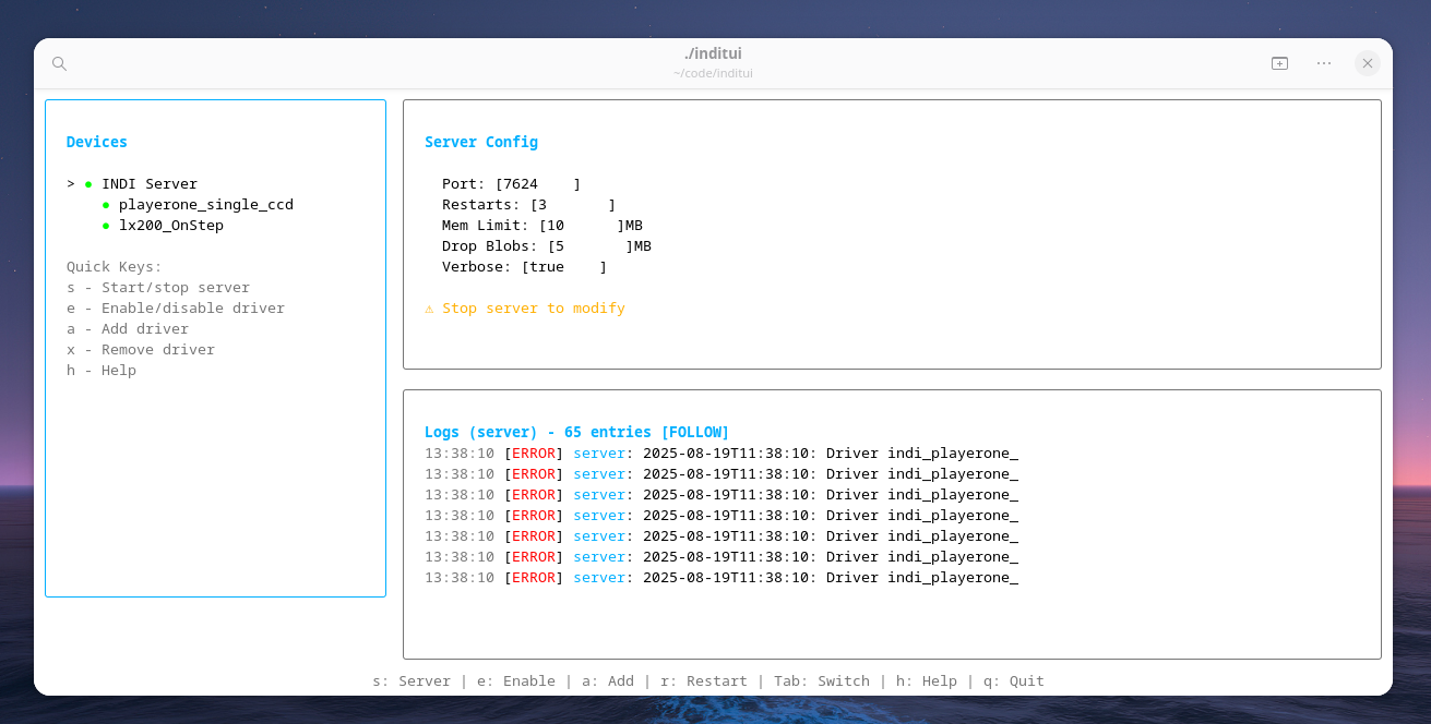
Cool project. What prompted you to write this? Asking because EKOS already has pretty good scheduling features (I've seen, not used). Along the way I did vibe-code a TUI for controlling the INDI server running on the MeLE 4C minicomputer attached to the telescope: https://www.svendewaerhert.com/content/blog/telescope-mount/... - I switched to a headless setup using a remote indi server after having a bad experience with reliability using remote desktop in Gnome. I'll probably put this TUI on Github once I clean it up a bit.
I am a professional astronomer, and I am running a survey for asteroids. This needs to be controlled from python, as it decides every night which objects to observe.
I also heavily use Jupyter for analysis, and with this code I can take over the telescope and command it in a jupyter session, allowing me to do live data analysis.
Great project!
The cost of the PCBs must be driven by assembly, right? The board itself should qualify for JLCPCB's budget offer at least: 2 layers (judging by the KiCAD-screenshot), < 100mm, HASL, nothing special about solder mask or board thickness either from the look of it. I'm not not sure about the plated slots of the USB connector, though? Do these cost extra?
How many did you get assembled per version? Just two of the boards or all five of them? Did you try to stick to using the standard parts or extended library? Which difference would it have made to do some work on the PCBs yourself, e.g. by soldering the through-hole connectors by hand?
Either way, it is definitely an amazing project!
Edit: as soon as any part is from the extended library, all different components (even standard ones) incur a cost for loading them into the pick and place machine, right? So minimizing number of different components is the only way of keeping the cost down, I guess.
Indeed the cost is mainly from assembly. The board itself is 2 layers, all default settings at Jlcpcb except for the color which is now black as opposed to the default green. This increases the cost of the board a bit. You can experiment with their calculator to find out more. I've ordered 5x each version, which is also the minimal order amount. I did try to stick to the standard library as much as possible but it's not easy once you go beyond standard passive components. Can't currently tell the exact difference it would made if I had soldered the THT by myself, likely not enough for me to bother. You could be right on that last part. The details on it are not as fresh in my head anymore. It is definitely true that you want to minimize the amount of different components. If you need 4k and 6k resistors you're better off buying 2x2k and 3x2k instead.
I love this so much. Is there any open-source software that calculates where a given planet or star might be (based on your coordinates) and automatically finds the star / planet and then follows it? Can these mounts be used with such software if it exists?
Stellarium and Kstars (which has EKOS built in) are both very good planetarium software. Both can interface with indiserver, which can talk to many astronomy devices such as mounts, filter wheels, cameras. I use Kstars mainly for controlling the mount, and Stellarium mainly for finding nice targets.
Yes, the OnStep firmware used here has drivers for ASCOM and Indi, which are communications protocols commonly used by most astronomy software on Windows and Linux. It also speaks the older Meade LX200 serial protocol, which is another common method.
For example, Stellarium on your phone can connect to the mount’s wifi station and control it.
> Is there any open-source software that calculates where a given planet or star might be (based on your coordinates)
Sure. Skyfield is a python library to calculate that (among others). Right on the front page is an example how to calculate the azimuth and elevation of Mars: https://rhodesmill.org/skyfield/
You could sell kits for this btw. There would be demand. And I think you could be quite successful.
The reason is that Trump is tariffing the hell out of the main Chinese telescope accessories manufacturer, ZWO. So if you can provide a non-Chinese alternative....
Think of trying to be Prusa 3D solution in the astrophotography area.
Nice. Harmonic drives are my 'favourite' machine element. The lash is silly and watching the carrier(?) deform is hypnotic.
Cool project. Strain wave mounts are fantastic. Just ordered a wave 150i myself. Can’t wait to not having to waste time balancing my scope anymore.
Loved the write up, well done to the author. I get the same feeling building stuff with freecad and then printing it. Feels like there is no limit to what can be done. After going through the growing pains of designing stuff that was just poor and difficult to print I’m now confident enough to send it to be printed by jlcpcb or pcbway. And when they tell me to accept the risk of a failed print then I think, “I feel your pain, good luck”. So far I have never gotten a failed print back. Maybe a little warped but way better than my attempts. If I never have to use my large resin printer ever again I will be happy.
On the pcb front, I dread going through those final steps in the pcb ordering process. No matter how many parts I preorder, there is always something that is unavailable. So much churn in component availability.
Thanks, glad you enjoyed this. It's good to be in a place where you're confident things will turn out alright when you send your designs halfway across the world to be manufactured. I've so far only had positive experiences with JLCPCB, especially with issues that turn up during their review process. I forgot to add a fillet around the edge where the DEC axis sticks out of the tube and they sent me a quick message to say "We can't guarantee a 100% right angle here cause of the minimum radius of our bits". I assumed they would just gloss over this and manufacture it anyway, but they gave me a chance to review it just in case it was important to the design (it wasn't in this case, but still). On the PCB side, I used a plugin for KiCAD that automatically generates the production files and the bom.csv - It's really critical to review this when you load it into their tool because the automatic recognition/matching with components sometimes has mistakes in it.
I built a small two axis direct-drive mount (https://mjbots.com/ controllers are great) to track satellites and aircraft with an RF antenna. One of the things that stood out in the article for me was the yolo send to JLCPCB. It spoke volumes about your confidence in the CAD design, maybe one of these days I'll get there hahaha.
Great design and writeup btw, it looks as good if not better than most of the commercial designs out there. You might enjoy Bruce Van Deventer's vids on youtube: https://www.youtube.com/@djcheckonetwo/videos (direct drive mount with 26 bit renishaw ring encoder might whet your appetite a bit)
Thanks for the compliment and links! Can you tell me more about the aircraft tracking? I've been toying with the idea of being able to select a nearby airplane on flightradar24 and instructing the mount to follow it as it comes into view. Not sure how I would even begin building that.
You could actually build a self-contained unit with a raspberry pi and a rtlsdr based receiver. They do a great job picking up ADSB directly from aircraft 100+ miles away.
You'd just need to write some glue code to take the ADSB streams from a given plane (could pick based on area or strongest signal or whatever) and convert that to alt/az from your reference frame to feed the motor controllers for tracking. Your mount would clearly be adequate for optical tracking so you'd want to add some smoothing and likely some kind of tracking corrections/trim but you'd be close right off the bat.
After using standard EQ-mounts for so long, seeing something without a counter weight just looks wrong to my neanderthal brain. My current mount weighs 40lbs, the counter weight is 17lbs, and the tripod legs are 20lbs. So that's over 75lbs of weight and size of gear to move around every time it goes on a road trip. This design looks like it was a fraction of that. Color me intrigued
I estimate a load capacity of 8-10kg. It's not designed for the really big equipment cause I also would like to take it on camping trips. If I were to do this again I will definitely add a threaded hole to mount a counterweight bar. I've noticed the tracking accuracy drop slightly when the mount is in the most overhanging positions.
It looks like you have a typical OTA attached, what camera are you using with that? I've only ever used my DLSR attached to the OTA for prime photography, but it is heavy. I've learned to test the position by hand of the camera through the full rotation to see how the orientation of the camera will change throughout the night to prevent hanging situations and so it has forward tension. I noticed more backlash type issues when it had reverse tension. The one thing I haven't done yet, is to just attached the camera to a small ball head to do tracked wide angle images. However, I really haven't done any dark sky shooting in many years, pre-Starlink. I wonder if long tracked exposures with wide angles would ever not be affected by Starlink trails
I switch between the cheap Byomic 76/700 newton and my Sigma 600mm lens (Canon EF but using an adapter to fit the Olympus body). I tried to get the DSLR looking into the newtonian but it was just too heavy, causing the plastic focuser to simply bend way off axis. I've since bought a dedicated astro camera (Neptune C II) which fits alright on the newtonian. I'm keeping the Byomic 76 only for visual observations now. Looking to buy a proper refractor of around 480mm. The Sigma 600 does alright with the DSLR but isn't very sharp, hard to focus and suffering from some coma. It's good enough to learn the ropes for now.
Yeah, in astro, the quality of the lens shows in much more disappointing ways that regular photography. Any softness from the lens can be part of the art in regular photography, but in astro is a lesser image.
Maybe I missed it, but where in Europe are you? Are the temps part of your softness issue? I'm in Texas, and during the summer when it's prime time for central part of the Milky Way the seeing is horrible from the extreme high temps and the disturbance it causes in the air.
I've been looking at getting a dedicated astro camera as well to reduce that weight as well as free up the camera body to go back to its primary mission of time lapse. I've already gone down the rabbit hole deep enough to have a secondary scope and camera to use as a guide scope to overcome any of the slight mis-alignments during polar alignment. The hole is deep and easy to fall into. Be careful when looking down that hole wondering how far you'd be willing to go as you'll be deeper than you expected before you realize you've left the edge.
Yeah I didn't expect such a stark difference in image quality from the same lens when using it for day photography vs astrophotography. Just goes to show how incredible a proper astrograph is. I'm located in Belgium: high light pollution and very humid skies. The only targets worth bothering here are close to zenith. It's a fun rabbit hole to be in :)
At my home, it is so light polluted, I don't even bother with attempts at zenith objects. I joke about every hotel in town is a 5-star hotel because you can literally only see 5 stars at night. With a 4 hour drive, I can be in one of the darkest spots in the state. To get to the darkest, it would be at least 8 hours. Either way though, it's Texas, so the high temps play havoc on image quality.
> slight mis-alignments during polar alignment
For long enough observation there is no such thing as correct polar alignment on earth, thanks to atmospheric lensing. The density of the atmosphere shifts stars up with increasing amounts depending on how low they are.
If your mount can accurately track in dec, then using a more complete pointing model-- the accommodates this lensing along with the major mount orthogonality errors-- generally eliminates the need for a guide camera.
Just for comparison:
I've got a Juwei-17 (Onstep harmonic drive with performance similar to the ZWO AM5N, but at nearly half the price) paired with the ZWO TC4 carbon fibre tripod.
The tripod has a load capacity of 50 kg (110 lbs) and weighs just 2.5 kg (5.5 lbs). The harmonic drive mount has a load capacity of 13 kg (29 lbs), or 18 kg (lbs) with a counterweight, and weighs 5.5 kg (12 lbs). Alltogether, the setup weighs about 8 kg (18 lbs) since I don't have to use counterweights.
This post reminds me of the beauty of open source. Well done build and a great project summary!
So is the accuracy and stability he achieved better or worse than the commercial mount?
Short answer: it's in the same ballpark as other mounts of the same size. The theoretical accuracy for RA is 0.198″ (65,536 steps and 100:1 reduction) and for DEC is 0.253″ (256*200 steps, 100:1). In practice many things will reduce this accuracy: seeing, proper polar alignment, sturdiness of the wedge and tripod all account for some loss in accuracy. My highest achieved accuracy was probably around 1″ during brief moments, I'm sure with excellent seeing this could reach <1″ performance.
So do you think that complex mechanism ended up no better than the normal mounts? It could be execution too, I am no good at experiments and sometimes even "proven" designs end up a bit subpar, so it could be the design was alright.
Not sure what you mean with complex mechanism. The mount has a similar architecture to other commercially available mounts like the HEM15 iPolar for example.
Oh ok. I didn't know harmonic drives were standard in commercial mounts.
They have become popular in the last few years. They are smaller, lighter and thus more portable than traditional mounts. They also don’t need to be balanced with a counter-weight (although they usually allow for a counter weight to increase payload capacity, they don’t need to be perfectly balanced). This all saves in set-up time.
One disadvantage compared to traditional mounts is that they absolutely need guidance, and with a pretty fast guide loop at that (like 0.5s). You can’t do long unguided exposures with a strain wave. But anyone who’s serious about astrophotography is guiding anyway so that’s not really a big deal.
I am a bit idly curious since I plan to build a telescope sometime. Nothing as complex as this, just a manually guided dobson.
I would encourage the author to share the kicad board and freecad parts on github.